3.1 Overall light path system design
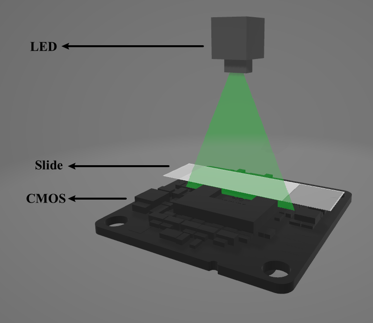
The diagram below illustrates the light path of the digital microscope, starting with an LED that provides a stable source of light. This light illuminates the specimen mounted on a slide, and the interaction between the light and the sample is captured by the CMOS.
In order to have multi-wavelength light, there are several ways to complete this system. One is to let the LED become multi-wavelength so that it can emit different light on a different wavelength. Another is to add a multiple-filter control system, including a plate holding filter of different wavelengths and a servo. By turning the plate so that light passes through different filters, the different wavelengths of light can be achieved.
3.2 Hardware and circuit design
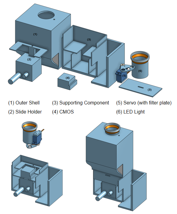
The whole system contains a total of six components without the Micro Control Unit (MCU), mainly including the outer shell, slide holder, CMOS, servo with filter, and LED. The adjustable holder (2) is an instrument that can change the height of the plate precisely. To switch between different filters, a servo is used to rotate the plate to choose the filter. The LED light shell is designed to hold one white LED with an aluminum base. To connect the system with the MCU, the positive and negative wires of the servo and the positive wire of the LED are directly connected to the 5V and GND ports in the MCU. The signal wire of the servo is connected to the analog output port of the MCU, and the negative wire of the LED is connected to the digital output port of the MCU. By programming the MCU to control the related output in different ports, the LED switch and the position of the servo can be controlled. The output wire of the CMOS can be directly connected to the computer to record the picture captured, or if the MCU is Raspberry Pi or similar hardware that has USB-A and wireless communication equipment, the CMOS could also directly connect to the MCU and wirelessly read data on a computer for later analysis.
3.3 3D printing and prototype building
For the outer shell, slide holder, and filter plate, the 3D printing material is photosensitive resin using the SLA process. An SG90 servo is used in this system because of its small size. A 5050 LED is used since it can separately control all three RGB values, and the distance between three small LEDs is in an acceptable range. A narrowband filter is used since a limited wavelength is required for the phase retrieving process to be accurate. The half-band width of the three filters is 20nm, and the wavelength for the three filters is 650nm, 532nm, and 450nm. The CMOS type is Basler dart daA2500-14um (No-Mount), with resolution (H x V) 2592 px × 1944 px, pixel Size (H x V) 2.2 μm × 2.2 μm, frame rate 14 fps, and mono color.
In order to assemble the system, the slide holder should be inserted into the supporting component in the middle bottom hole and fixed with glue. The CMOS and its supporting components should be fixed with a screw and nut. The wire should be appropriately carried out by drilling holes in the supporting component. After making sure the output port of the CMOS is exposed and gluing the front board of the supporting component on, assemble the filter plate with all three filters, and then attach the filter plate to the servo. Then, screw the servo and its supporting component to the outer shell, and make sure all wires are correctly connected as stated in the “Hardware and circuit design” section. Finally, assemble the outer shell with the supporting component, and do the first test of the system.